NOTIFIER Emergency Radio Communications Bi-Directional Amplifier (BDA)
NOTIFIER BDA, Bi-Directional Amplifier System, is a signal boosting solution designed to enhance in-building radio frequency (RF) signal coverage for public safety radio.
Reliable Two-Way Emergency Radio Communication with NOTIFIER BDA
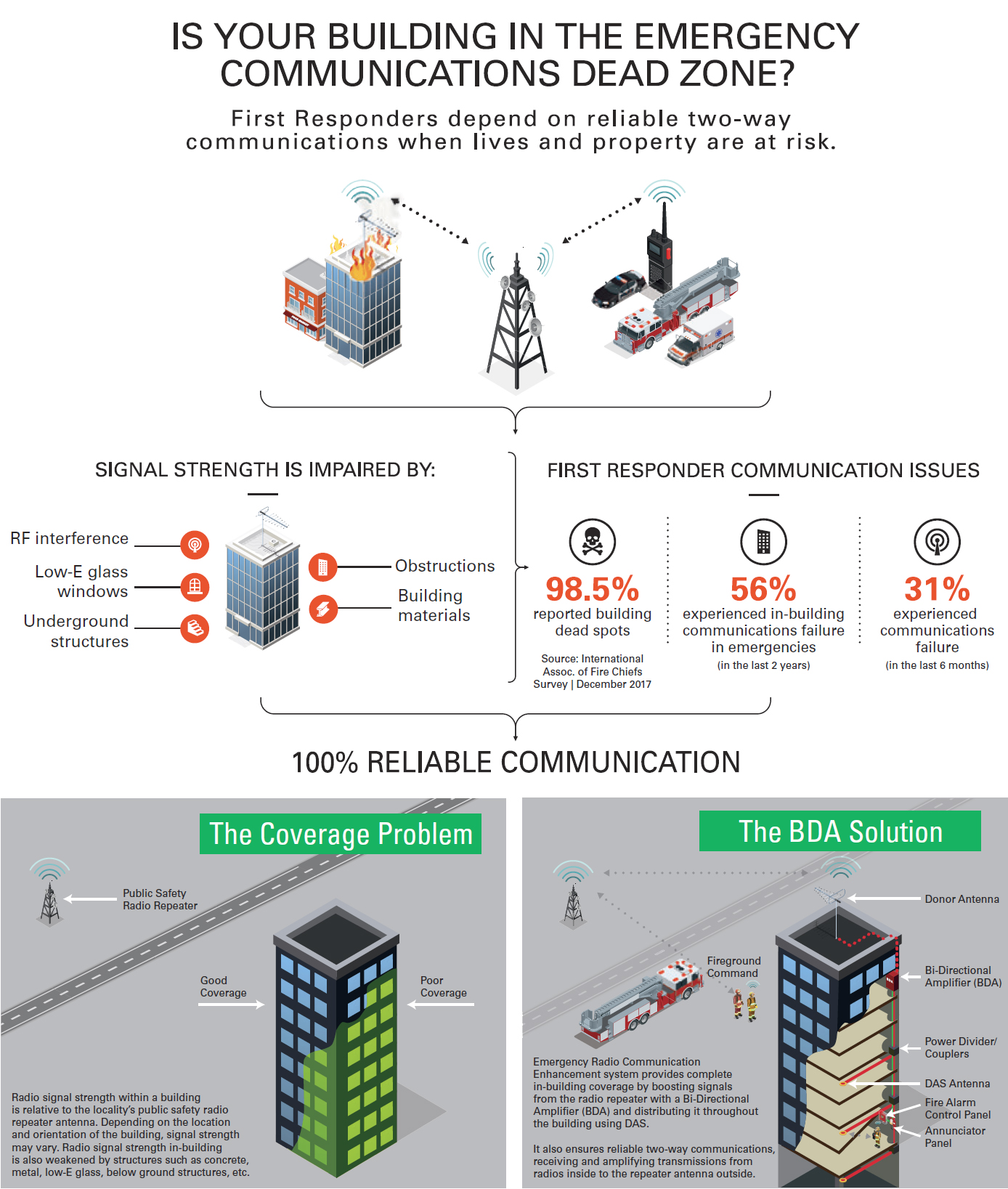
Emergency Responders lose communications when radio signals in-building are weakened by structures such as concrete, windows, and metal. Staying informed with clear radio transmissions between first responders inside of a building and emergency personnel outside of the building can help prevent injuries and save lives.
NOTIFIER’s Bi-Directional Amplifier (BDA) System is a signal boosting solution designed to enhance in-building radio frequency (RF) signal coverage for public safety radio. When combined with industry leading fire systems, NOTIFIER provides the reliability and quality expected from a life safety solution.
Reliable Performance
Specifically designed to meet UL2524 In-building 2-Way Emergency Radio Communication Enhancement Systems, NOTIFIER’s Class B, Bi-Directional Amplifier Solutions provide a high power, band-selective radio signal booster system that can be designed and customized to meet all public safety frequency band ranges. This state of the art BDA System is developed to provide a high rejection of interfering signals, and is designed for excellent heat dissipation, corrosion resistance and ease of wall-mounting.
NOTIFIER BDA Bi Directional Amplifier ERCES for First Responders (3:45 min)
NOTIFIER BDA Features & Benefits
Specifically designed to meet NFPA and IBC/IFC code compliance with a UL2524 2nd Edition listing, NOTIFIER’s BDA and Fiber DAS solution enhances two-way radio signal strength inside buildings, tunnels, and other structures. This solution offers a Digital Class A/B, low to high power (0.5W to 5W) radio signal booster system that can be customized to meet all public safety frequency band ranges (VHF, UHF, 700 MHz, 800 MHz, and FirstNet Band 14 support with Single/Dual Band). This state-of-the-art BDA and Fiber DAS System provides the best amplification and coverage performance and supports the reliability of the radio network with no noise.
A complete portfolio that offers all components required to meet any single or multi-building application nationwide, supporting all public safety frequency bands, and at a lower total cost to own.
IFC, IBC, and NFPA compliant, FCC certified
UL2524 2nd Edition listing for In-building 2-Way Emergency Radio Communication Enhancement Systems
Channel selective, software programmable, or adjustable bandwidths. Platform wide Downlink Automatic Gain Control (AGC) per channel and time slot
Built-In NOTIFIER addressable monitor module for direct integration to NOTIFIER Fire Alarm Control Panel for monitoring BDA and Fiber DAS Master/Remote. Dedicated annunciator options include a built-in annunciator in Battery Backup Unit (BBU) and a remote annunciator.
No noise, oscillation prevention and monitoring with programmable performance mitigation actions and automatic uplink power amplifier auto-off support for safe operation and non-interference with the public safety radio system
Directly integrates with NOTIFIER Fire Alarm Control Panel
Single BDA to cover multiple sub-bands with a wider bandpass
Automatic and self-adjusting oscillation prevention and uplink squelch support
Lower power consumption for long term reliability and efficiency
Infographic: Is Your Building in the Emergency Communications Dead Zone?
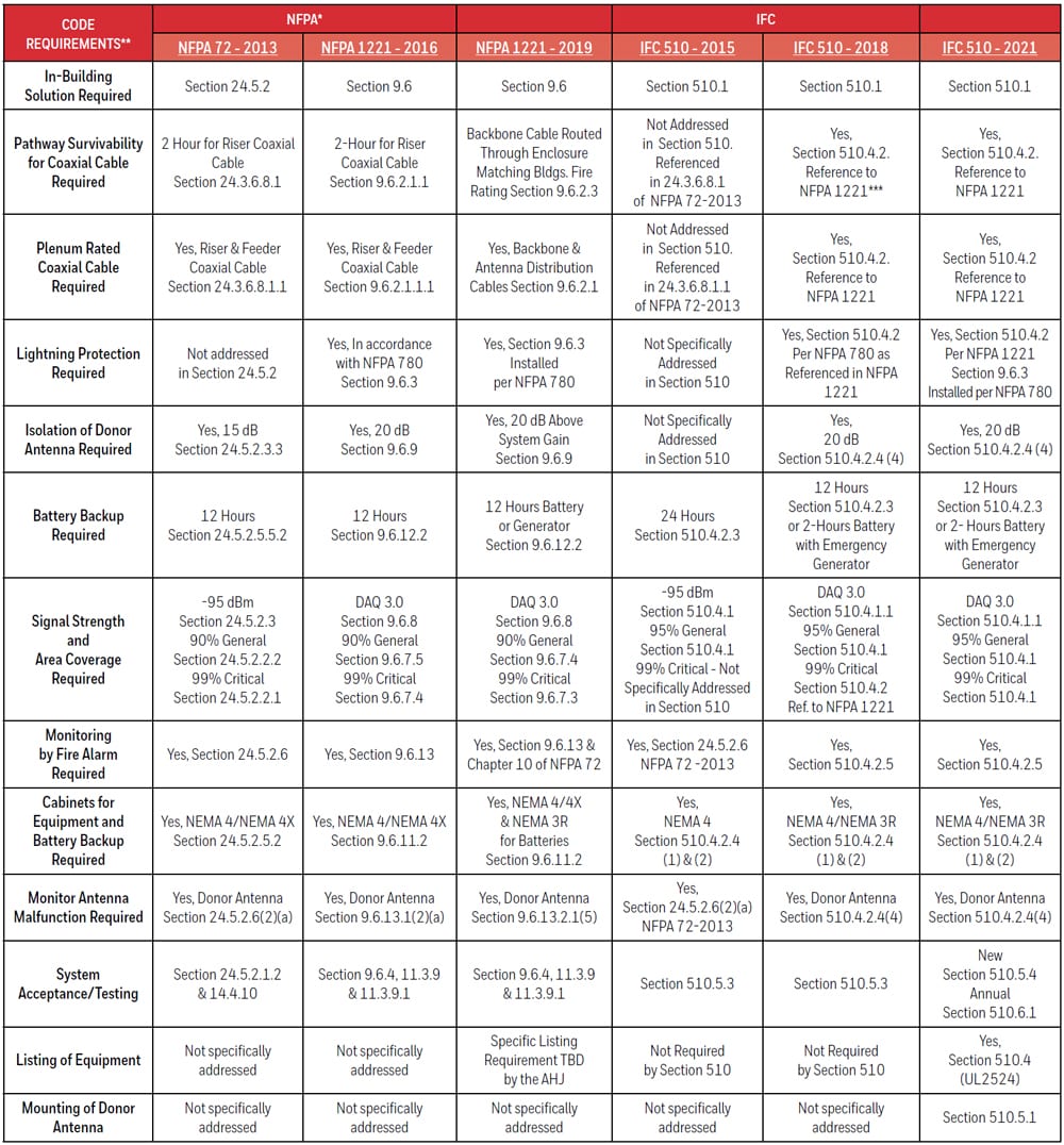
BDA Codes & Standards
Reference Guide
Most current adopted Building Codes and Installation Standards require Emergency Responder Radio Signal strength and coverage to be measured in all new and some existing construction. This Reference Guide provides a summary of the key requirements in the national consensus model codes and installation standards that govern the installation, testing and maintenance of in-building emergency responder radio enhancement systems. Always consult with your local fire jurisdiction to determine if other local specifications or ordinances are followed which could be more stringent than the ones listed below.
* 2021 NFPA 1 Section 11.10: In all new and existing buildings, minimum radio signal strength for emergency services department communications shall be maintained at a level determined by the AHJ. Where required by the AHJ, in-building emergency responder communication enhancement systems shall comply with Section 9.6 of NFPA 1221 and 11.10.3.1 through 11.10.5 of 2021 NFPA 1; shall be listed and labeled in accordance with UL 2524, In-building 2-Way Emergency Radio Communication Enhancement Systems.
*** Also See NFPA 1221 TIA 16-2.
BDA Code Requirements and Product Standards
Emergency Responder Communication Enhancement Systems (ERCES) were first introduced in the International Building Code (IBC) 2009. The ERCES requirement was established to address the performance of emergency responders’ portable radios inside buildings because building construction, building size, construction features, and other elements can absorb or block radio communications.
Today’s codes like the IBC 2021 Section 916, NFPA 1 2021 Section 11.10, IFC 2021 Section 510, 2019 NFPA 1221 Section 9.6 or 2022 NFPA 1225 Chapter 18 require all buildings to have an approved level of radio coverage within the building based on the existing coverage levels of the public safety communication systems of the jurisdiction at the exterior of the building. This coverage can be achieved by enhancing the in-building radio frequency signal coverage with an ERCES, which is comprised of a BDA / Signal Booster and Distributed Antenna System (DAS).
UL2524 product performance listing and standard was only recently introduced for ERCES. UL2524 2nd Edition listing from an OSHA approved Nationally Recognized Testing Laboratory (NRTL) provides AHJs, A&Es, and building owners the assurance from an independent third-party organization that systems are code compliant and installed BDA systems will provide reliable communications for emergency responders.
UL 2524 In-building 2-Way Emergency Radio Communication Enhancement Systems – Technical Requirements
Areas Addressed by UL 2524:
Safety (risk of fire and risk of shock) requirements–construction and testing
Compliance with specific performance requirements in accordance with the IFC-2018 and NFPA 1221-2016 (2019)
Reliability performance requirements applicable for life safety systems – construction and testing
Product marking and installation documentation
Scope:
Cover products (e.g. repeater, transmitter, receiver, signal booster components, remote annunciators and operational consoles, power supply, and battery charging system components) used for in-building 2-way radio emergency radio communication enhancement systems installed in a location to improve wireless communication at that location.
Does not cover passive RF components which are defined in UL 2524 as “any device that RF passes through that does not have an active electronic component that requires external power. This includes, antennas, splitters, couplers, coaxial cable and connectors. Passive components cannot amplify RF signals.”
Performance – Operation:
Normal AC power
Visual and audible annunciation within 200 secs of fault for Loss of normal AC power, Battery charger failure, Loss of battery capacity (to 70% depletion), Donor antenna disconnection, Active RF emitting device malfunction, System component malfunction other than passive RF component which affects system performance
Visual & audible annunciation within 24 hours of fault for Donor antenna malfunction
Construction:
NEMA Type 4 or 4X for all repeater, transmitter, receiver, signal booster components, external filters, and battery system components. Note: Rechargeable standby batteries are permitted to be contained in enclosures that comply with the requirements for a Type 3R.
The system shall be sufficiently modular to have the capability to support revised and/or additional system frequencies within the same frequency band of the bi-directional amplifier supplied to maintain radio system coverage as it was originally intended without the need to replace the system.
Reliability:
Variable Voltage Operation Test
Variable Ambient Temperature and Humidity Tests
Component Temperatures Test
Charging Current Test
Transient Testing
BDA FAQs
What are NFPA’s requirements for annunciator at the FACP or is FACP monitoring adequate?
A dedicated annunciator panel must be located in the fire command center or other location designated by the AHJ. The BDA and Fiber DAS Master/Remote status must also be monitored by the building’s fire alarm system.
Does the Building Code require BDAs for Police and Fire Departments?
The code requires coverage for Emergency Responders. The AHJ will determine which Emergency Responder agencies need to be included in the system. Generally, it includes Fire, Fire Mutual Aid, Police and EMS.
Who determines what public safety agencies are to be supported under the provisions for “Emergency Responder Radio Coverage”?
The AHJ will determine which agencies will need coverage.
What skills, education, or experience must a technician have to install, commission, and service a BDA system?
This depends on the jurisdiction, but typically FCC GROL or approved equivalent and manufacturer certification.
How to Determine if a BDA System is Beneficial to Your Building
An RF Survey must be conducted. Typically performed by specialized FCC GROL certified technician or fire department radio personnel, an RF Survey is performed by measuring the Downlink/Uplink signal strengths in decibels-milliwatts (dBm) using special measuring devices. Signal strengths can be determined before building construction starts by completing the survey on the building site, followed by software-simulated radio propagation modeling resulting in heat maps that show predicted signal coverage levels. Results are submitted to AHJ to determine if a BDA is required or if a waiver is appropriate.
BDA System Components
The All-Inclusive BDA Solution from NOTIFIER
Lives depend on reliable public safety radio coverage. Enhance in-building coverage with NOTIFIER’s UL 2524 listed. Bi-Directional Amplifier (BDA).
NOTIFIER offers all the components required for design and installation of the Emergency Radio Communication Enhancement Systems (ERCES): signal boosters/bi-directional amplifiers (BDA), batteries and battery enclosures, donor antennas, Distributed Antenna Systems (DAS), coaxial cables, connectors and lightning arrestors, power dividers and hybrid couplers.
Signal Boosters / Bi-Directional Amplifiers (BDA)
NOTIFIER Class B BDAs are high gain, high power band-selective signal boosters/bi-directional amplifiers that can be designed and customized to meet all public safety frequency band ranges. It is intended to provide reliable two-way radio signal coverage inside buildings, tunnels and other structures. The band selective design delivers a reliable performance in even the most challenging RF environments.
Features:
All public safety frequency bands supported, various models available
UL, CSFM, NFPA, IFC compliance
High Reliability
Excellent RF Performance
Serviceability
Expandability
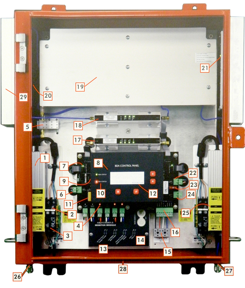
Inside the Panel:
Primary Power Supply, 28V
Primary Circuit Breaker ON/OFF Switch
Primary Circuit Breaker
Trouble Status Indication LEDs – Normally OFF
Donor Antenna Line Integrity Sensor
28VDC Input from Primary Power Supply
DC 28V Power indication for Uplink Power Amplifier – Normally ON
Control panel
SD Card – Stores History Logs with Time Stamp
BDA and Power Supply Status LEDs – Normally GREEN
On-board 47k EOL resistors Enable/Disable
LCD – Indicates Primary PSU Voltage, Secondary PSU Voltage, System Voltage, Battery Voltage, Battery Current, Time and Date, UL/DL Gain and Power, PSU Status, BDA status, System Logs and History
Addressable Monitoring Module (Compatible with Honeywell Farenhyt, Gamewell-FCI, Notifier).
Address Set Rotary Switches and LED Status Indications
SLC Loop Circuit
Annunciator Panel Connection
Downlink Amplifier Module with LED Status Indications
Uplink Amplifier Module with LED Status Indications
Duplexers under Protective Cover Plate
Uplink Power Amplifier with LED Status Indication (Normally Green LED ON). Red or OFF = Failure. Plinking Red = Over temperature Warning
Downlink Power Amplifier with LED Status Indication (Normally Green LED ON). Red or OFF = Failure. Blinking Red = Over temperature Warning
27.4V DC Input from Secondary Power Supply / Charger
FUSE for Battery Supply Line
Battery Wire Connection (24V / 75Ah SLA)
Secondary Power Supply / Battery Charger
Donor Antenna Connection (N-Female)
DAS Connection
Cutouts for ½” Conduit: Primary 120V, Annunciator and FA Wiring, Battery Wires and Secondary 120V Circuits
Heatsinks
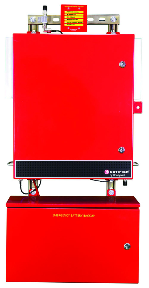
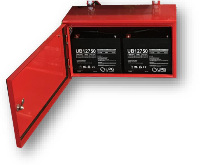
Battery Backup
All signal boosters come with a fully integrated battery charger and battery diagnostics functions.
OEM Battery backup enclosure is provided with the BDA
Designed to fit below the BDA
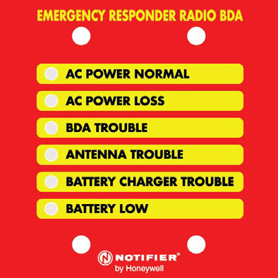
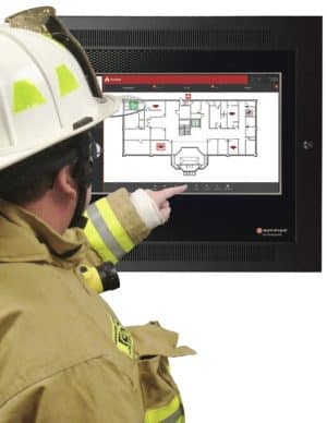
Annunciator Panel
Dedicated monitoring panel is required
Specified in NFPA 72 and 1221
Independent from fire alarm system
Powered by the BDA power supply and battery
OEM panel included with the BDA
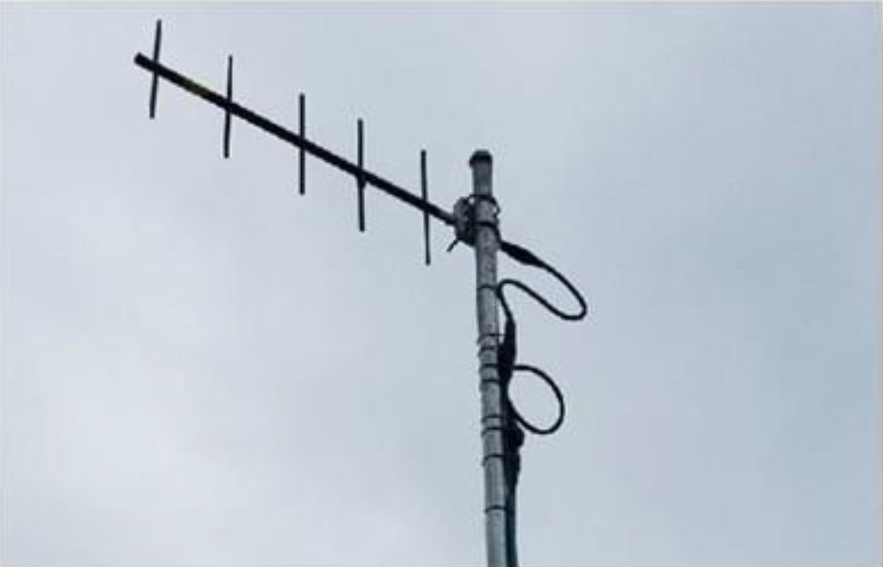
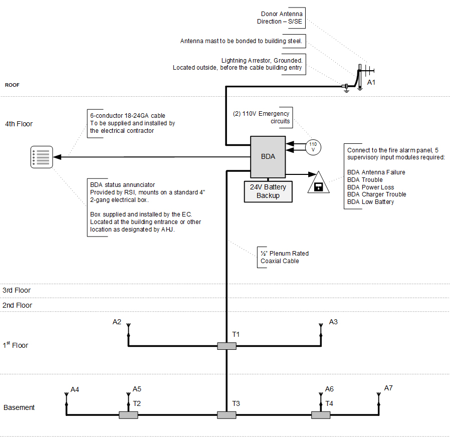
Donor Antenna
Installed on the Roof of the building
Pointing to the public safety radio repeater site
High gain, high directivity
Does not need line of sight
Coaxial Cable
Typically Plenum Rated, ½” diameter
Low insertion loss is required
We now use red cable
Some AHJs have special labeling requirements
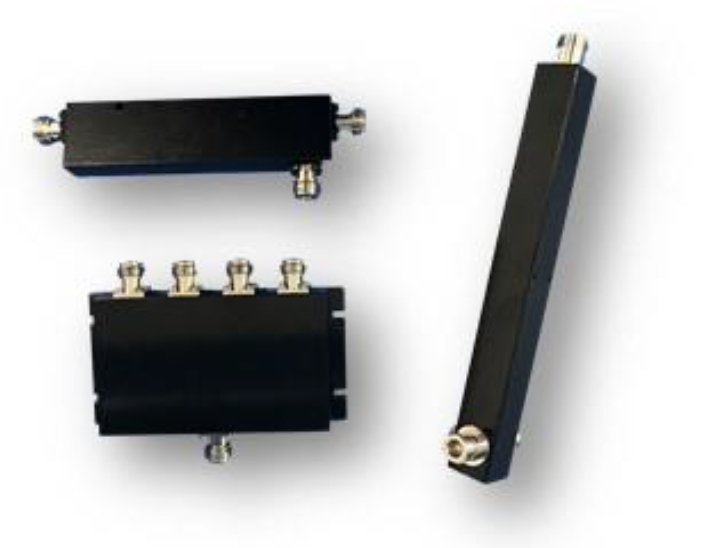
Signal Splitters and Couplers
Used for signal distribution
Come in different coupling values
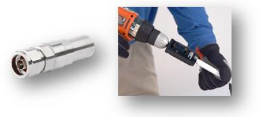
RF Connectors
Installed using specialized tool
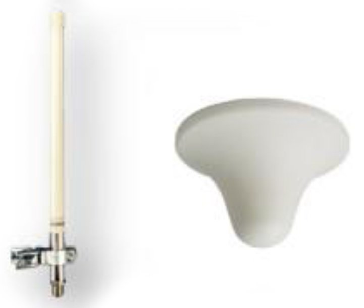
DAS Antennas
Fiberglass “stick” antennas have the best performance